Hardware walkthrough
The Solana Badge, module by module.
An ESP32-S3 badge built for DEF CON — a 2.8″ SPI display, six buttons behind an I²C expander, stereo PDM microphones, addressable RGB, an NXP secure element, USB-C with Li-Po charging, and a header that hands you everything left over.
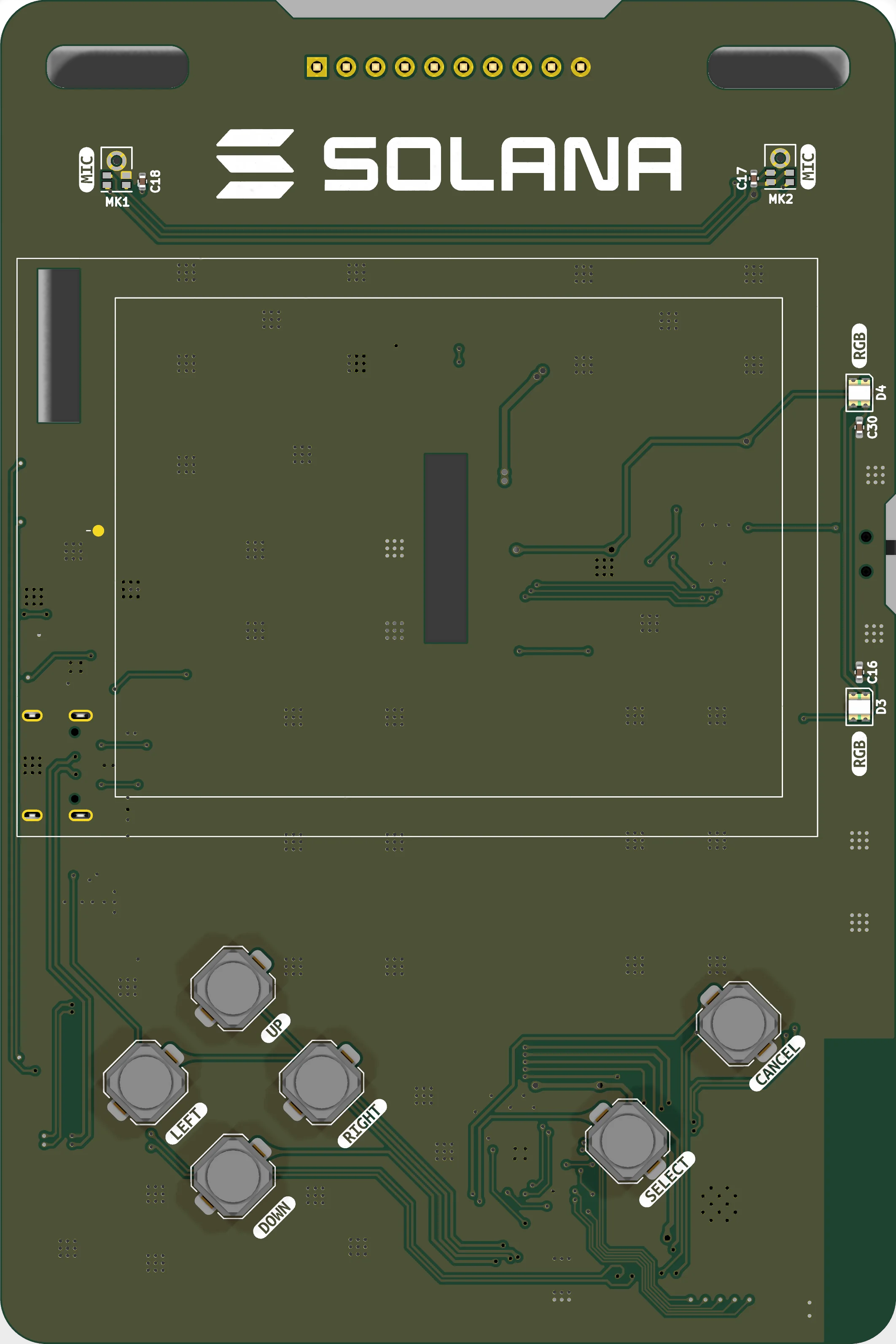
Every highlight on the board below is placed straight from the KiCad layout, so what you see marked is the part that is actually there.
- Revision
- v1 · rev "lcd"
- Outline
- 77.6 × 116.3 mm
- Stackup
- 2 layers, 1.6 mm
- MCU
- ESP32-S3-WROOM-1-N16R8
Nine modules
Front face carries the display, the buttons, the microphones and the RGB. Everything else — the module itself, power, USB and the secure element — lives on the back.
- 01 Compute ESP32-S3 module Dual-core Xtensa LX7 with 16 MB flash and 8 MB octal PSRAM, Wi-Fi and Bluetooth LE. back
- 02 Display 2.8" SPI LCD ILI9341 240×320 panel on an 18-pin FPC, with a transistor-switched backlight. back
- 03 Input Six buttons over I²C A D-pad plus select and cancel, read through a TCA9534 expander rather than GPIO. front
- 04 Audio Stereo PDM microphones Two SPH0641LM4H bottom-ports sharing one data line, one channel per clock edge. front
- 05 Light Addressable RGB Two WS2812B-compatible LEDs daisy-chained off a single pin. front
- 06 Security SE050 secure element An NXP EdgeLock SE050C2 on the I²C bus for key storage and crypto. back
- 07 Connectivity USB-C and serial One USB-C port, two possible owners, and a slide switch to pick between them. back
- 08 Power Battery and power path Li-Po charging, protection, an ORing power path into a 3V3 LDO, and an ADC tap. back
- 09 Expansion J7 header Eight free GPIO plus VSYS and ground on a 2.54 mm strip along the top edge. back