← → to move between modules
07 / 09 · Connectivity
USB-C and serial
One USB-C port, two possible owners, and a slide switch to pick between them.
- Port
- USB-C 2.0, 16P
- Bridge
- CH340C (U3)
- Selector
- S1 · DPDT
- Native USB
- GPIO19 / GPIO20
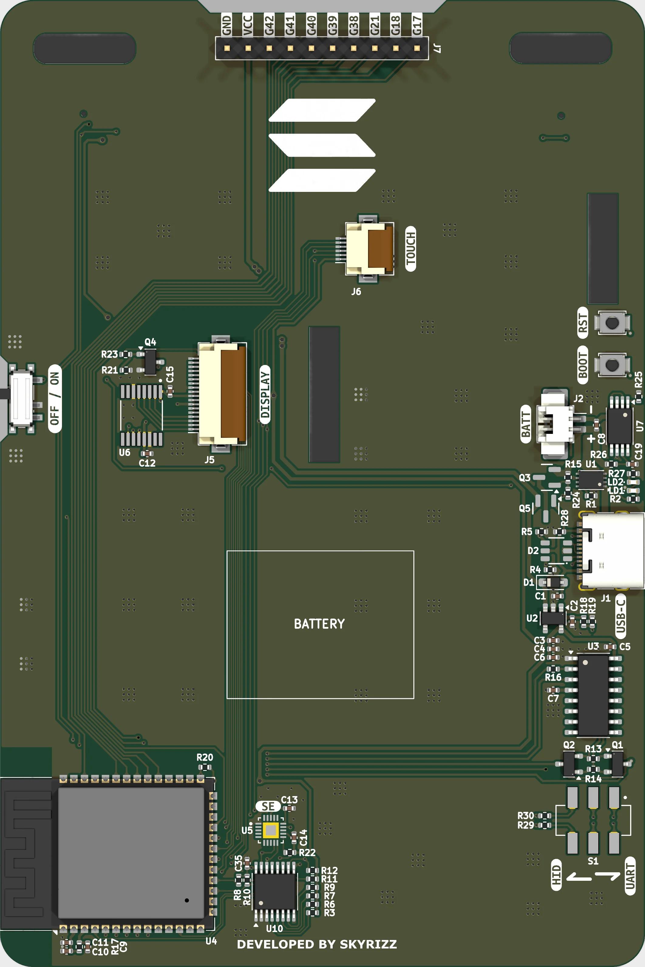
J1 is the only data port on the badge, and S1 decides who gets it. The connector's D+/D− pair — ESD-protected by D2, with 5K1 CC resistors R4/R5 — routes either to the CH340C USB-serial bridge or straight to the ESP32-S3's native USB pins through 22 Ω series resistors R29/R30.
The two paths are mutually exclusive. Flip S1 toward UART and you get a classic serial port with auto-programming: Q1 and Q2 translate the CH340C's DTR and RTS into GPIO0 and EN, so esptool can reset the chip into download mode without anyone touching a button. Flip it toward HID and the ESP32 enumerates directly — USB CDC, TinyUSB, DFU, HID.
Which way you leave it depends on what the badge is being. UART is the position for putting firmware on it and reading a log back out. HID is where it sits once it has firmware: enumerating as a USB device in its own right is what lets the badge work as a hardware wallet, because the Ed25519 key is generated inside the SE050 and its public key is the badge's Solana address — a host can hand it a transaction to sign and the private key never crosses the connector.
BOOT1 and RST1 are the manual version of the same thing: hold BOOT1, tap RST1, release BOOT1. UART0 on GPIO43/44 stays wired to the CH340C throughout, and the firmware mirrors its log to both UART0 and the USB CDC port so a board can be diagnosed over whichever one you have.
Pins
| Pin | Net | Role | Function |
|---|---|---|---|
| GPIO19 | ED− | USB D− | Native USB D−, through 22 Ω R29 to S1. |
| GPIO20 | ED+ | USB D+ | Native USB D+, through 22 Ω R30 to S1. |
| GPIO43 | TX0 | UART0 TX | UART0 TX to the CH340C for upload and serial monitor. |
| GPIO44 | RX0 | UART0 RX | UART0 RX from the CH340C via 220 Ω series R16. |
Parts
- J1 USB-C receptacle, USB 2.0 16P Power in and the single data pair
- S1 MST-22D18G2 DPDT slide switch — routes D+/D− to the CH340C or to native USB
- U3 CH340C USB-to-UART bridge on UART0
- D2 SRV05-4 ESD protection on the USB data pair
- Q1 / Q2 SS8050 Auto-program circuit — DTR → GPIO0, RTS → EN
- BOOT1 / RST1 B3U-1000P Manual download-mode and reset buttons
Notes
- Native USB and CH340C serial cannot be active at the same time — the switch is the arbiter.
- Solana OS already signs with the SE050 key — it is how a badge proves itself to the broker — but that runs over Wi-Fi. Signing over the USB HID interface is what the switch position is for; it is not in the shipped firmware yet.
- You can still flash with S1 on the HID side, but nothing drives GPIO0 and EN for you: pick the “Native USB” reset mode and put the board into the bootloader by hand.
- The USB HID mouse path in the test firmware only compiles under the USB-OTG / TinyUSB USB mode; the default Hardware CDC build reports “HID OFF” and skips it.