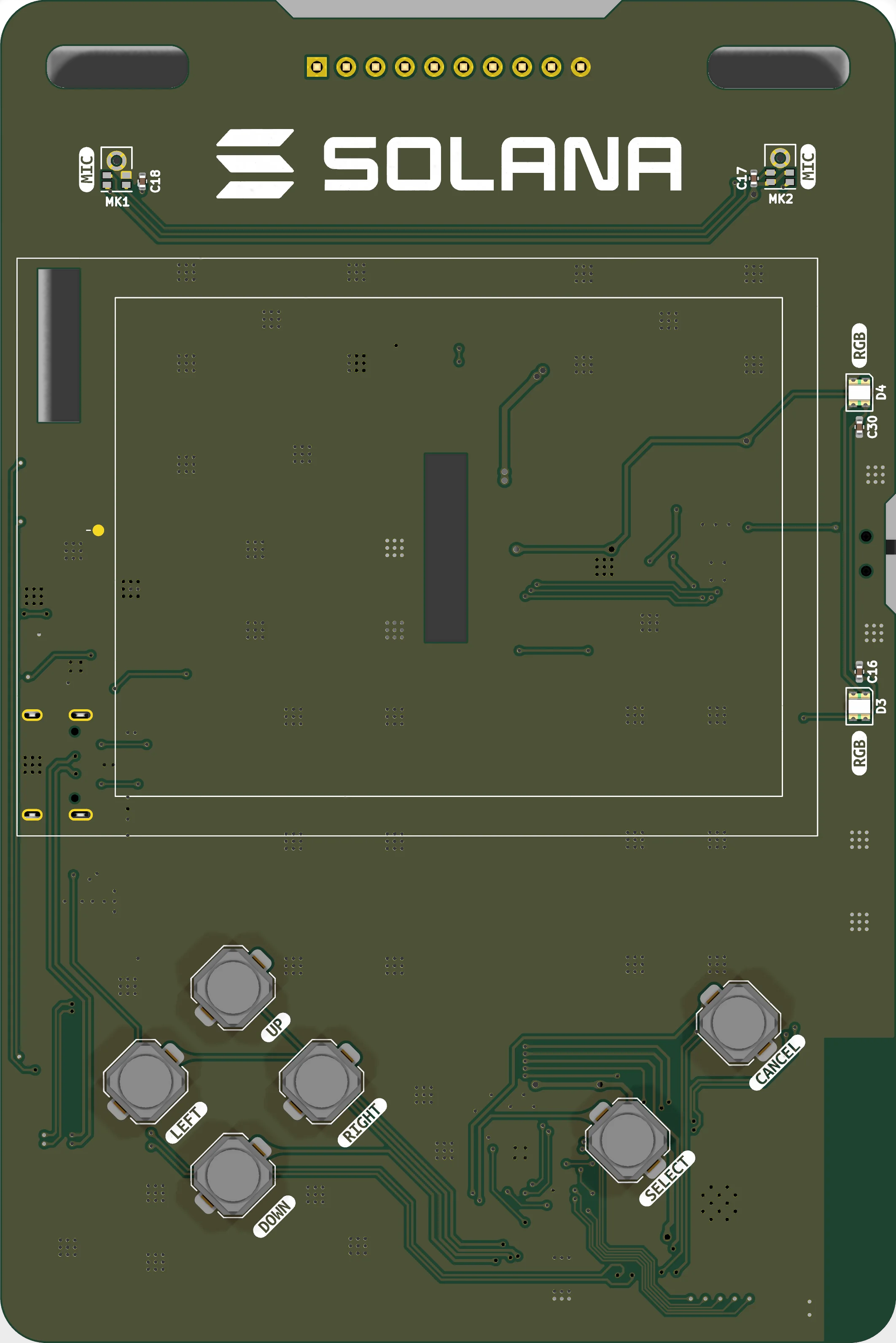
MK1
MK2
C17
C18
← → to move between modules
04 / 09 · Audio
Stereo PDM microphones
Two SPH0641LM4H bottom-ports sharing one data line, one channel per clock edge.
- Mics
- 2 × SPH0641LM4H
- Interface
- PDM, 2 wires
- Sample rate
- 16 kHz
- Pins
- GPIO47 / GPIO48
MK1 and MK2 sit at the top corners of the front face, as far apart as the outline allows, which is what makes stereo capture meaningful on a board this size.
Both microphones share the same clock and the same data line. MK1 has its SELECT pin tied to GND and MK2 has it tied to 3V3, so one drives the data line on the rising clock edge and the other on the falling edge. The I²S peripheral in PDM mode de-interleaves them into a stereo pair.
This moved in the v1 revision. The microphones used to sit on GPIO19/20 and collided with native USB; on GPIO47/48 audio and USB can now run at the same time.
Pins
| Pin | Net | Role | Function |
|---|---|---|---|
| GPIO47 | MICSCK | MIC CLK | PDM clock, shared by both mics (MK1 pin 4, MK2 pin 4). |
| GPIO48 | MICSDI | MIC DATA | PDM data, shared line (MK1 pin 1, MK2 pin 1). One channel per clock edge. |
Parts
- MK1 SPH0641LM4H-1 Left channel — SELECT tied LOW
- MK2 SPH0641LM4H-1 Right channel — SELECT tied HIGH
- C17 / C18 100n Supply decoupling, one per microphone
Firmware
constexpr int      PIN_MIC_CLK      = 47;
constexpr int      PIN_MIC_DATA     = 48;
constexpr uint16_t PDM_SAMPLE_RATE  = 16000;
constexpr bool     MIC_SWAP_LR      = false;
Notes
- The test kit captures both channels and draws live level bars on the LCD (serial command “m”).