← → to move between modules
01 / 09 · Compute
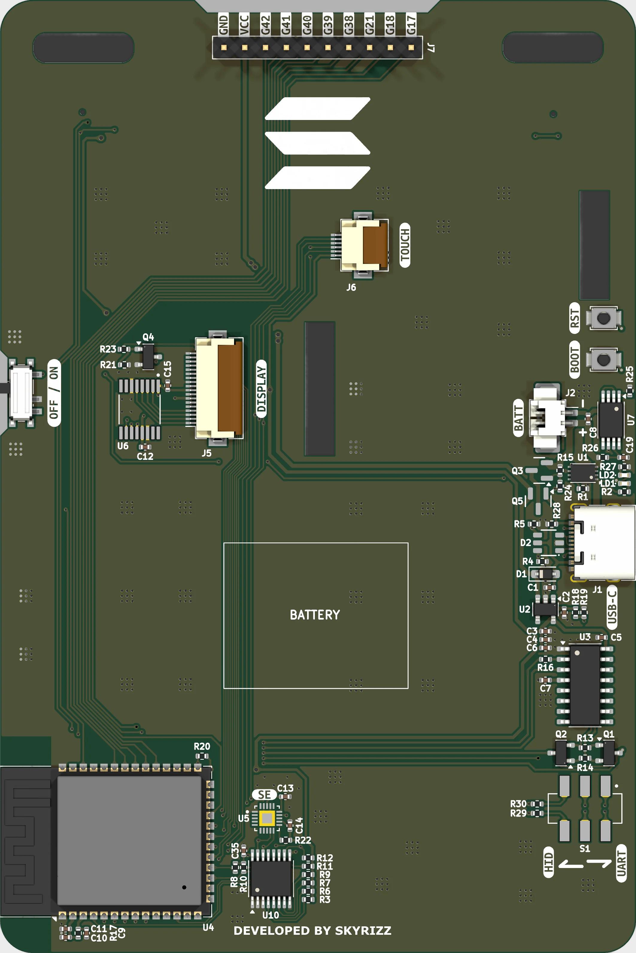
ESP32-S3 module
Dual-core Xtensa LX7 with 16 MB flash and 8 MB octal PSRAM, Wi-Fi and Bluetooth LE.
- Part
- ESP32-S3-WROOM-1-N16R8
- Flash
- 16 MB
- PSRAM
- 8 MB octal
- Radios
- Wi-Fi · BLE 5
Everything on the badge hangs off U4. The module sits along the bottom edge of the back face with its antenna overhanging the board cutout, so nothing else is routed underneath it.
Two straps decide how the badge boots. EN is the reset line, tied to the RST1 button and to Q2 of the CH340C auto-program circuit. GPIO0 is the download-mode strap, pulled up by R20 and driven by Q1 from the same circuit — which is why holding BOOT1 and tapping RST1 drops the board into the ROM bootloader.
The N16R8 variant spends GPIO35, GPIO36 and GPIO37 on its internal octal PSRAM. They are not brought out anywhere and must be left alone.
Pins
| Pin | Net | Role | Function |
|---|---|---|---|
| EN | EN | RESET | Reset / enable. RST1 button plus Q2 (CH340C RTS). |
| GPIO0 | IO0 | BOOT | Download-mode strap. 10K pull-up R20, driven by Q1 (CH340C DTR). Do not use during boot. |
| GPIO35 | — | PSRAM | Internal octal PSRAM. Reserved. |
| GPIO36 | — | PSRAM | Internal octal PSRAM. Reserved. |
| GPIO37 | — | PSRAM | Internal octal PSRAM. Reserved. |
| GPIO3 | — | NC | Not connected. Strapping pin (JTAG source select) — leave floating at boot. |
| GPIO45 | — | NC | Not connected. Strapping pin (VDD_SPI voltage) — do not pull at boot. |
| GPIO46 | — | NC | Not connected. Strapping pin (ROM messages) — do not pull at boot. |
Parts
- U4 ESP32-S3-WROOM-1-N16R8 Application processor, Wi-Fi/BLE radio, flash and PSRAM
Notes
- Build target: ESP32-S3 with 16 MB flash and 8 MB PSRAM (N16R8).
- GPIO5 and GPIO6 were the touch-controller interrupt and reset. Touch is unpopulated on this build, so both are free.