← → to move between modules
05 / 09 · Light
Addressable RGB
Two WS2812B-compatible LEDs daisy-chained off a single pin.
- LEDs
- 2 × XL-0807RGBC-2812B
- Protocol
- WS2812B, single wire
- Pin
- GPIO2
- Placement
- Right edge, front
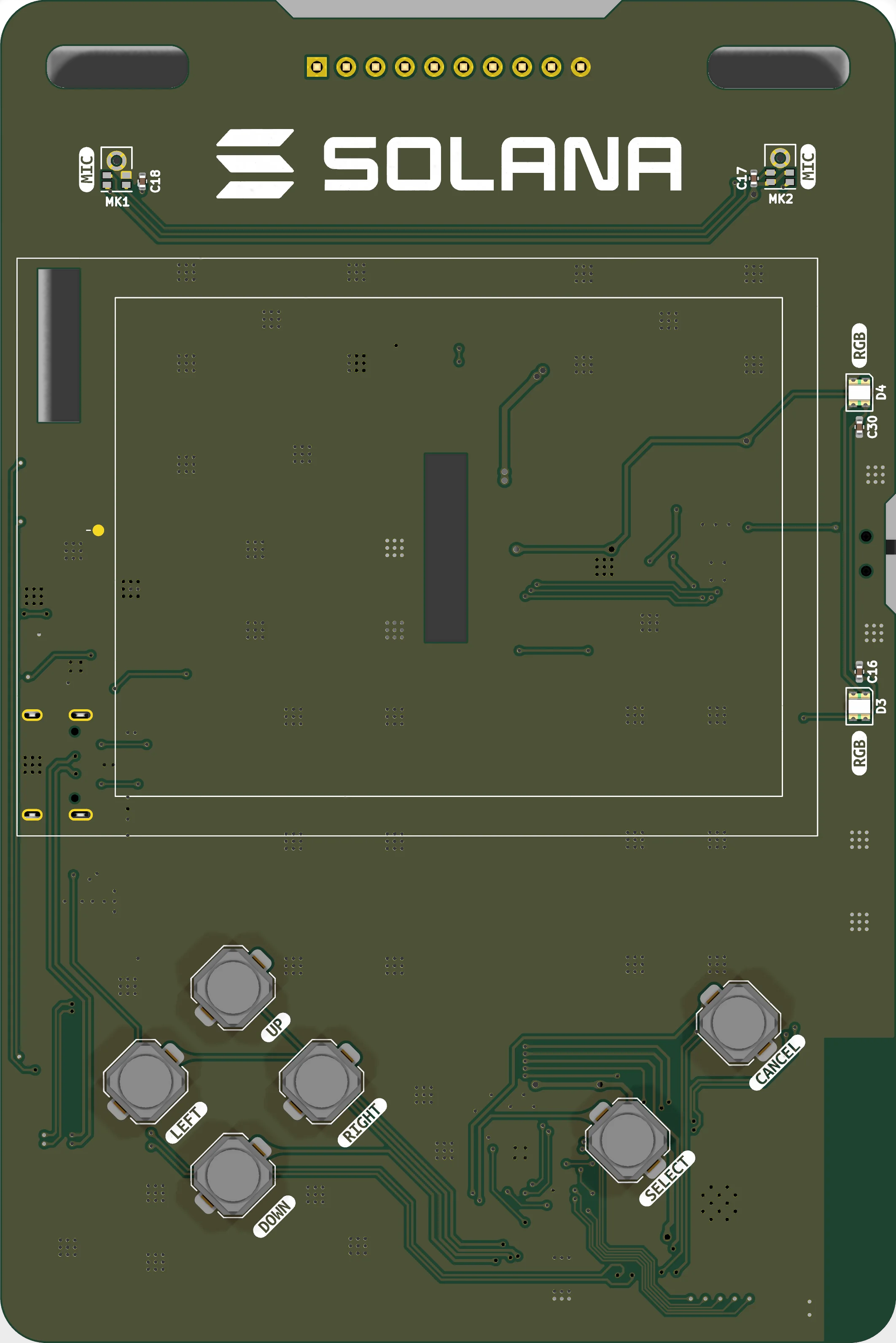
GPIO2 drives D3; D3 passes its DOUT into D4. One pin, two independently addressable pixels, 24 bits of colour each.
The protocol has no clock, so the whole thing is timing: a few hundred nanoseconds per bit, 60µs for a two-pixel frame. The test firmware bit-bangs that straight against the GPIO registers with interrupts held off, which is fine on a board doing nothing else.
Solana OS drives the same two LEDs through the RMT peripheral instead. It runs Wi-Fi and BLE, and their high-priority interrupts are not masked by disabling interrupts the usual way — one landing mid-frame stretches a pulse and corrupts every bit after it, which shows up as the second LED in the chain flickering while the first looks fine. RMT clocks the frame out in hardware, so an interrupt can delay a frame but can no longer corrupt one.
Both LEDs are on the front face along the right edge, so they read as accent lighting either side of the display.
Pins
| Pin | Net | Role | Function |
|---|---|---|---|
| GPIO2 | I02 | WS2812 | Data into D3; D3 DOUT daisy-chains into D4. |
Parts
- D3 XL-0807RGBC-2812B First pixel in the chain
- D4 XL-0807RGBC-2812B Second pixel, fed from D3 DOUT
- C16 / C30 100n Supply decoupling, one per LED
Firmware
constexpr int     PIN_RGB        = 2;
constexpr uint8_t LED_BRIGHTNESS = 72;